Optical power budget: will this optic make your link?
An 8 km link with four patch points: will an LR do, or is it marginal? How to work out power budget, link loss and margin, with three worked examples.
You have an 8 km link with four patch points along the way and you want to know whether a plain 10G LR will make it. Or the link is already up, flaps now and then, and you suspect it's simply marginal. Both are five minutes of arithmetic. Below: the calculation as a checklist, sourced values per kilometer, connector and splice, and three worked examples.
Two numbers: budget and loss
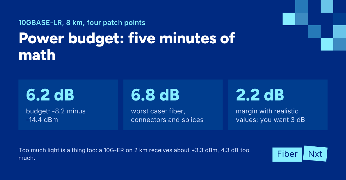
An optic's power budgetPower budget The difference in dB between an optic's minimum transmit power and its receiver sensitivity: the loss the link may have. Link loss plus margin must stay within it. is its minimum transmit power minus its receiver sensitivity. For 10GBASE-LR that's -8.2 dBm minus -14.4 dBm, so 6.2 dB. That's the loss your link can have while the optic is guaranteed to work. Most modules do better, but you don't plan on it.
Against that you set the link loss: fiber attenuation per km times length, plus every connector pair, plus every splice. A patch panel or cross-connect adds at least one connector pair. What's left over is your margin.
One trap: some datasheets also list a maximum channel insertion loss, and it can be lower. Cisco's 1G BX10 works out to 10.5 dB on paper (-9 minus -19.5 dBm) but guarantees only 5.5 to 6 dB of channel insertion loss; Cisco doesn't count the rest as usable link loss. When both are given, use the lower number.
The second limit is maximum receive power: more light than that overloads the receiver. You check it against the lowest loss your link could have.
Which values to use
Calculate twice: once with the maxima from the standards, once with realistic values.
| Component | Worst case | Realistic |
|---|---|---|
| Single-mode, 1310 nm | 0.4 dB/km (G.652, TIA OS2 outside plant) | 0.36 dB/km (max. in a G.652.D cable datasheet) |
| Single-mode inside a building | 1.0 dB/km (TIA-568.3-D) | — |
| Connector pair | 0.75 dB (TIA-568.3-D) | 0.25 dB mean (IEC 61753-1 grade C) |
| Fusion splice | 0.3 dB (TIA-568.3-D) | under 0.05 dB (FOA) |
| Margin for aging and repairs | 3 dB (FOA) | — |
The 0.75 dB is generous, the FOA says as much. But designing on 0.25 dB assumes every connector is clean and stays that way.
Three worked examples
10G LR over 8 km, four connector pairs, two splices. Worst case: 8 × 0.4 = 3.2 dB of fiber, 4 × 0.75 = 3.0 dB of connectors, 2 × 0.3 = 0.6 dB of splices, 6.8 dB in total. That's 0.6 dB over budget. With realistic values you get 2.88 + 1.0 + 0.1 ≈ 4.0 dB and 2.2 dB of margin. It will probably work, but with less than the 3 dB you want. IEEE sized the LR budget with only 2 dB for all connectors and splices combined; four patch points fit only if they're clean. Overload is impossible with LR: maximum transmit power and maximum receive power are both +0.5 dBm.
1G BiDi BX20 over 14 km, two connector pairs, four splices. A Solid Optics BX20 transmits at least -9 dBm with a sensitivity of -20 dBm: 11 dB of budget. Worst case: 14 × 0.4 = 5.6 dB, plus 1.5 dB of connectors and 1.2 dB of splices, 8.3 dB in total. Margin 2.7 dB, realistically more than 5 dB. Overload can't happen: transmit power tops out at -3 dBm and the receiver handles at least -3 dBm. Do order a matching U/D pair, see BiDi pairs explained.
10G ER over 2 km, two connector pairs. Now the other limit matters. The ER transmits up to +4.0 dBm and may receive at most -1 dBm. With good connectors (2 × 0.12 dB, grade B) and 2 km of cable at 0.22 dB/km you lose about 0.7 dB. That puts +3.3 dBm on the receiver, 4.3 dB too much. With the 5 dB attenuator Cisco requires you land at -1.7 dBm: within spec, but tight. We'd simply fit an LR here. Worst case 2 × 0.4 + 1.5 = 2.3 dB of loss, 3.9 dB of margin, no attenuator.
The calculation as a checklist
- Find the minimum transmit power, receiver sensitivity, maximum receive power and, if listed, maximum channel insertion loss in the datasheet.
- Calculate the power budget: minimum transmit power minus sensitivity, or the channel insertion loss if that is lower.
- Count the path: length in km, every connector pair including patch panels and cross-connects, every splice.
- Calculate worst-case loss with 0.4 dB/km (1.0 inside a building), 0.75 dB per connector pair and 0.3 dB per splice.
- Subtract the loss from the budget and check that at least 3 dB of margin is left.
- Calculate the lowest plausible loss and subtract it from the maximum transmit power; if that exceeds the maximum receive power, fit an attenuator in each direction.
- Measure the link with a light source and power meter before you put it into service.
Measuring beats calculating
A calculation is an estimate. So measure insertion loss with a light source and power meter: that's your actual loss. If it disappoints, an OTDR trace shows where it sits: a bad splice at kilometer 3, or a dirty connector on the patch panel.
DOM/DDMDOM/DDM Digital Optical Monitoring / Digital Diagnostic Monitoring: the transceiver reports live temperature, supply voltage, laser bias current and transmit and receive power. is no substitute: SFF-8472 allows ±3 dB of measurement error. For a first impression it helps, though: Rx power minus sensitivity is roughly your margin (see reading DOM/DDM). If the link is already flapping, work through the SFP checklist first. Which reach goes with which distance is covered in reach codes.
Does it fit? The SFP-10G comes as LR and ER, the 1G BiDi as BX20 and BX40; more under 10G optics. They come from Solid Optics, a Dutch company, are tested in the Netherlands, on customer equipment too, and carry a lifetime warranty. Clean with a Clear Connection Tool. In doubt? Have the link measured through our services or call an engineer.

Founder of FiberNxt and Xyphen IT
Yvan Watchman is the founder of FiberNxt and Xyphen IT. He has been building and running networks and data centre infrastructure in and around Amsterdam for years.
Related products and services
Frequently asked questions
How do I calculate a transceiver's power budget?
Subtract the receiver sensitivity from the minimum transmit power in the datasheet. A 10GBASE-LR transmits at least -8.2 dBm with a sensitivity of -14.4 dBm, so 6.2 dB of budget. If the datasheet also lists a maximum channel insertion loss, use whichever number is lower.
How much margin should I keep?
The Fiber Optic Association recommends about 3 dB, to cover aging and future repair splices. Below that the link often still works, but there is little headroom when something changes.
When do I need an attenuator?
When maximum transmit power minus the lowest loss your link could have lands above the maximum receive power. That can't happen with an LR; it can with ER and ZR on short links. Cisco requires a 5 dB attenuator for its 10G-ER below 20 km.